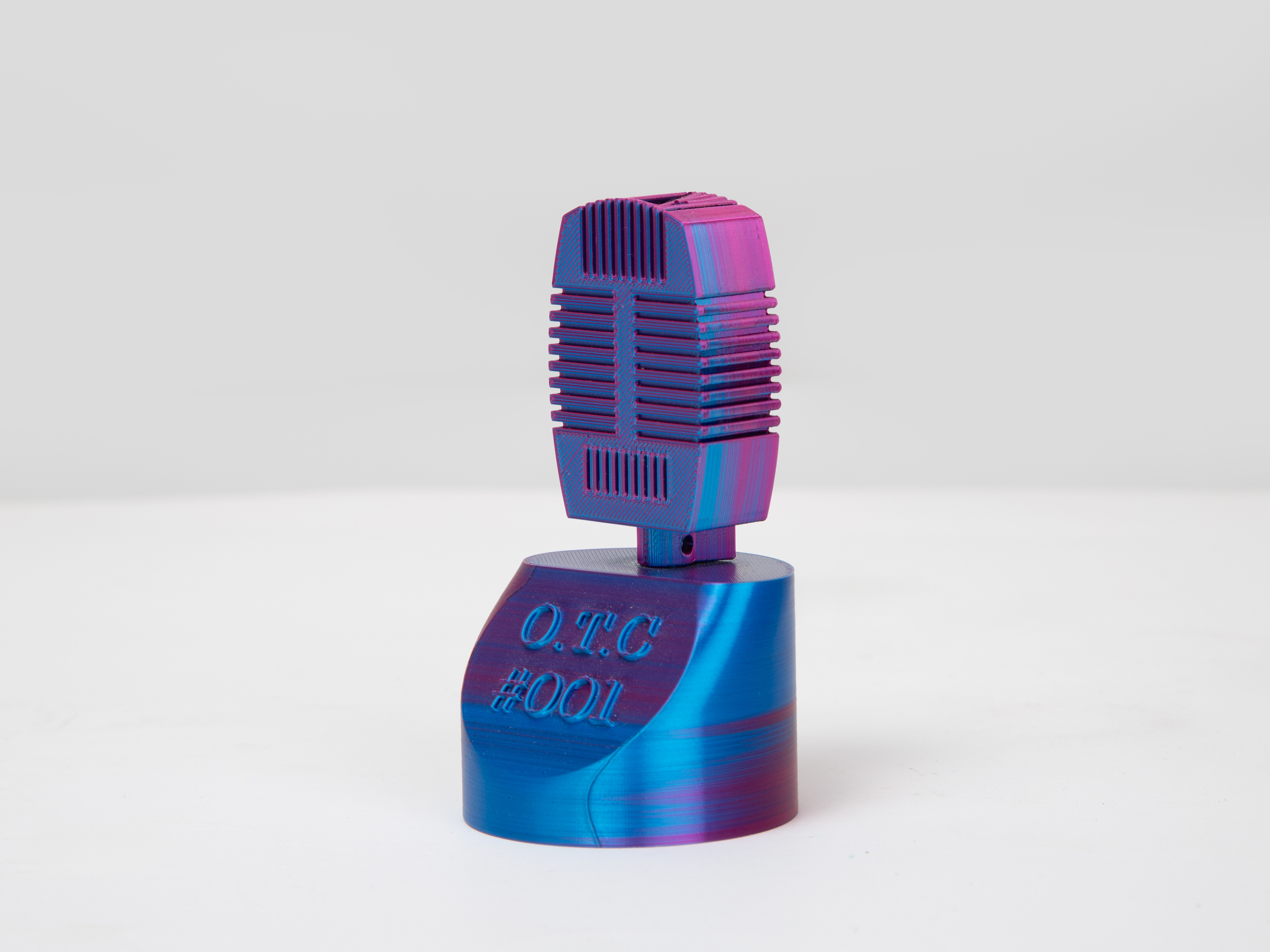
I designed and built a custom 3D printer to achieve an affordable device suitable for small-to-medium format applications. Though not intended as a commercial product, the project focused on developing a deeper understanding of mechanical engineering, electronics, and material science in modern additive manufacturing. Throughout the process, I learned to integrate hardware and software, troubleshoot effectively, and refine the printer's mechanical and control aspects. I enhanced my practical skills by facing and overcoming technical challenges and demonstrated perseverance, initiative, and adaptability.
Overall Design and Axis Configuration
The printer’s design drew on commonly available components and cost-effective solutions. I opted for 2020 aluminum extrusions as the frame material to achieve a stable yet affordable structure. While not as rigid as premium frames, these extrusions provided a reliable and versatile platform when carefully squared using precision squares, a bubble level, and digital calipers. Square nuts and adjustable brackets allowed for incremental refinements, and lightly PU-coated printed parts improved wear resistance and longevity despite lower-cost materials and less stringent tolerances.
The motion system balanced simplicity and functionality. The Z-axis employed an L-shaped support and dual lead screws driven by two NEMA 17 stepper motors wired in parallel. Although a more sophisticated system could have used independent drivers or closed-loop synchronization, this more straightforward approach lowered complexity. Repeated homing and incremental mechanical adjustments ensured both sides of the X-axis remained level within a fraction of a millimeter. Standard 8 mm smooth rods, LM8UU bearings, and GT2 belts provided cost-effective linear motion for the X and Y axes. These components were selected based on standard bed sizes (~200 x 200 mm) and moderate build heights. Although not as precise as high-grade linear rails, careful alignment, conservative print speeds, and occasional lubrication ensured smooth and consistent operation.
Material Choices and Printed Components
Parts subjected to higher mechanical loads or elevated temperatures—such as extruder mounts or components near the hotend—were printed from PETG or ABS to handle stress and heat. Less critical elements, like frame brackets or cable clips, were produced in PLA for easier printing and a better surface finish. To compensate for lower-cost materials, all printed parts received a light PU coating, improving wear resistance and durability over time. This approach allowed me to achieve acceptable performance from more economical components.
Stepper Motors, End-Stops, and Belt Tensioning
NEMA 17 stepper motors with around 40 N·cm torque and a 1.8° step angle were chosen for their widespread availability and compatibility with Arduino-based CNC shields. Though not as high-precision as more expensive motors, they delivered sufficient torque for the belt and lead screw configurations. Mechanical microswitch end-stops were integrated at the home positions of each axis. Adjusted via PU-coated printed mounts, these switches provided a simple, budget-friendly homing solution that, while slightly more variable than optical or hall-effect sensors, proved reliable for the intended application.
To maintain proper belt tension, I installed adjustable tensioner brackets. Belt tension was assessed by feel—lightly plucking the belt and comparing its “twang” to a reference established through experience. This rudimentary method was sufficient for a cost-conscious design. If bearings seated too tightly in printed parts, I reprinted those components with slightly adjusted tolerances or carefully filed the bore. Although these methods were less refined than professional gauges or press-fit fixtures, they aligned with the project’s emphasis on learning and resourcefulness.
Extruder, Hotend, and Cooling Setup
For the extruder and hotend, I selected a common all-metal hotend paired with a direct-drive extruder assembly. This configuration minimized filament retraction distances and improved flow control. A dedicated hotend cooling fan prevented heat creep, while a separate part-cooling fan enhanced print quality on bridges and overhangs. PU-coated fan mounts and cable clips kept wiring neat and away from the carriage’s travel path. I mitigated filament jams despite using more affordable components by tuning print temperatures, maintaining consistent filament diameters, and periodically cleaning the nozzle.
Throughout the project, each subsystem’s refinement—from frame assembly and axis design to hotend attachment and software configuration—demanded new problem-solving strategies and adaptive thinking. Experiencing setbacks, such as misalignments from a laser-cut frame or filament jams in the extruder, taught me resilience and the value of incremental improvements. I steadily advanced my understanding of the technology by experimenting with different materials, adjusting mechanical tolerances, and recalibrating the printer after each trial.
From a learning perspective, I developed foundational mechanical engineering skills through practical assembly tasks, gained electronics experience while integrating stepper drivers and end-stops, and improved my material science knowledge by selecting appropriate plastics and coatings. The project also honed my ability to plan activities, think critically, and persevere through challenges—key outcomes aligned with the project’s educational focus.
