STEAM TURBINE
I designed and built a small two-stage turbine driven by compressed air, intending it as a hands-on demonstration of fluid dynamics and multi-stage efficiency principles. The primary objective was not to produce a commercially viable device but to gain practical experience translating theoretical turbine concepts into a working model. From the outset, I needed to balance mechanical precision, flow management, and stage-to-stage energy transfer within a small footprint to illustrate how multiple stages can improve performance relative to a single-stage unit.
RESEARCH AND PLANNING
During the initial research and planning, I studied how steam turbines typically convert thermal energy into mechanical power, although I relied on compressed air rather than steam. I focused on adapting fundamental design considerations—such as optimizing blade angles, minimizing leakage, and managing pressure drops—to a low-temperature, low-pressure environment. This approach allowed me to concentrate on blade geometry and stage arrangement without the added complexity of high temperatures or corrosive working fluids. Designing a rough plan of the turbine geometry evoked excitement tempered by nervousness as I confronted the inherent intricacies of multi-stage flow interaction and the delicate interplay between rotor and stator arrays.
I employed 3D modeling and additive manufacturing techniques. To translate these concepts into physical form. The two rotor sets were fitted with airfoil-shaped blades to efficiently extract kinetic energy from the incoming airflow. At the same time, the two stators used U-shaped blades to redirect and stabilize the flow between stages. Ensuring structural integrity and printability required subtle design choices, including adding a ring around each blade assembly to prevent fragility and optimizing the blade count for torque generation and minimal turbulence. Close attention to tolerances was crucial, as even tiny misalignments could degrade efficiency through unintended gaps and frictional losses. Iterative refinements in the digital model helped preempt these issues before printing.
Assembly and Testing
Assembly revealed a host of practical lessons. The initial plan to secure rotors with screws gave way to a more straightforward press-fit approach, reducing complexity and improving the concentricity of the shaft. Despite these adjustments, small gaps between components remained a challenge. Insufficiently tight fits allowed pressurized air to escape or caused friction, limiting the maximum achievable rotational speed. I discovered that sanding was often necessary to fine-tune the clearances and that a vertical orientation during spin-up tests facilitated the removal of residual sanding particles. Moreover, balancing the mass distribution along the shaft became essential to overcoming frictional loads and ensuring smooth, stable rotation under operating pressures.
Testing the turbine against input pressures revealed a predictable relationship between inlet pressure and rotational speed. The turbine reached higher RPM values at higher pressures, confirming that increased energy availability from the compressed air supply translated into greater mechanical output. Temperature changes were also evident in adiabatic expansion, causing localized cooling condensation around the turbine body and imparting valuable insights into thermodynamic effects beyond pure mechanical design.
While absolute efficiency remained modest—hampered by the small scale, basic blade profiles, and rudimentary seals—each test run reinforced the validity of the fundamental principles guiding turbine design. The results suggested that more advanced manufacturing methods, perhaps CNC machining or improved sealing techniques, could significantly enhance performance. Exploring higher pressures, alternate blade geometries, or shifting from compressed air to steam at controlled conditions might further refine the system’s operational characteristics, pushing the design closer to the theoretical ideals studied in textbooks.
The project expanded my technical capabilities and deepened my understanding of fluid machinery. Iterative testing and data-driven decision-making resembled the refinement cycle standard in complex engineering endeavors. The process taught me to prioritize specific design parameters, accept incremental improvements, and adapt quickly when initial plans fail to deliver desired outcomes. This experience, while strictly educational and non-commercial, established a foundation of skills and insights that can be applied to future, more ambitious turbine developments. Ultimately, I learned that bringing a turbine from conceptual design to physical operation demands far more than theoretical knowledge. It requires an appreciation for material properties, fabrication constraints, and the subtleties of fluid-structure interactions.
Farnsworth FUSOR
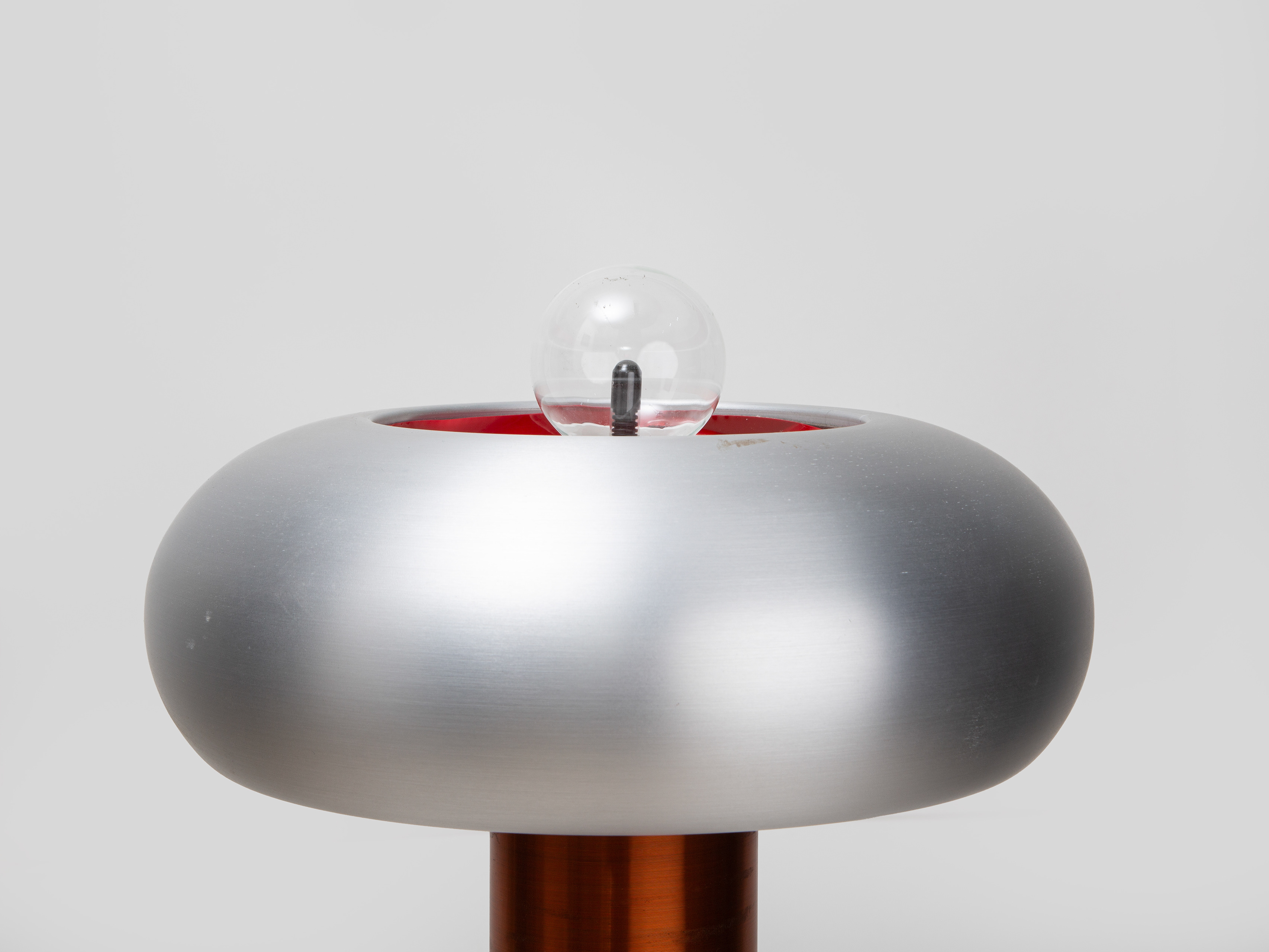
I constructed a Farnsworth-inspired fusor with a vertical electrode arrangement, aiming to create conditions for ion acceleration and potential fusion events using a high-voltage DC supply, vacuum, and controlled gas input. While the ultimate goal was not achieved, this process allowed me to gain practical experience in managing high-voltage systems, vacuum engineering, and gas handling techniques.
Design and Materials
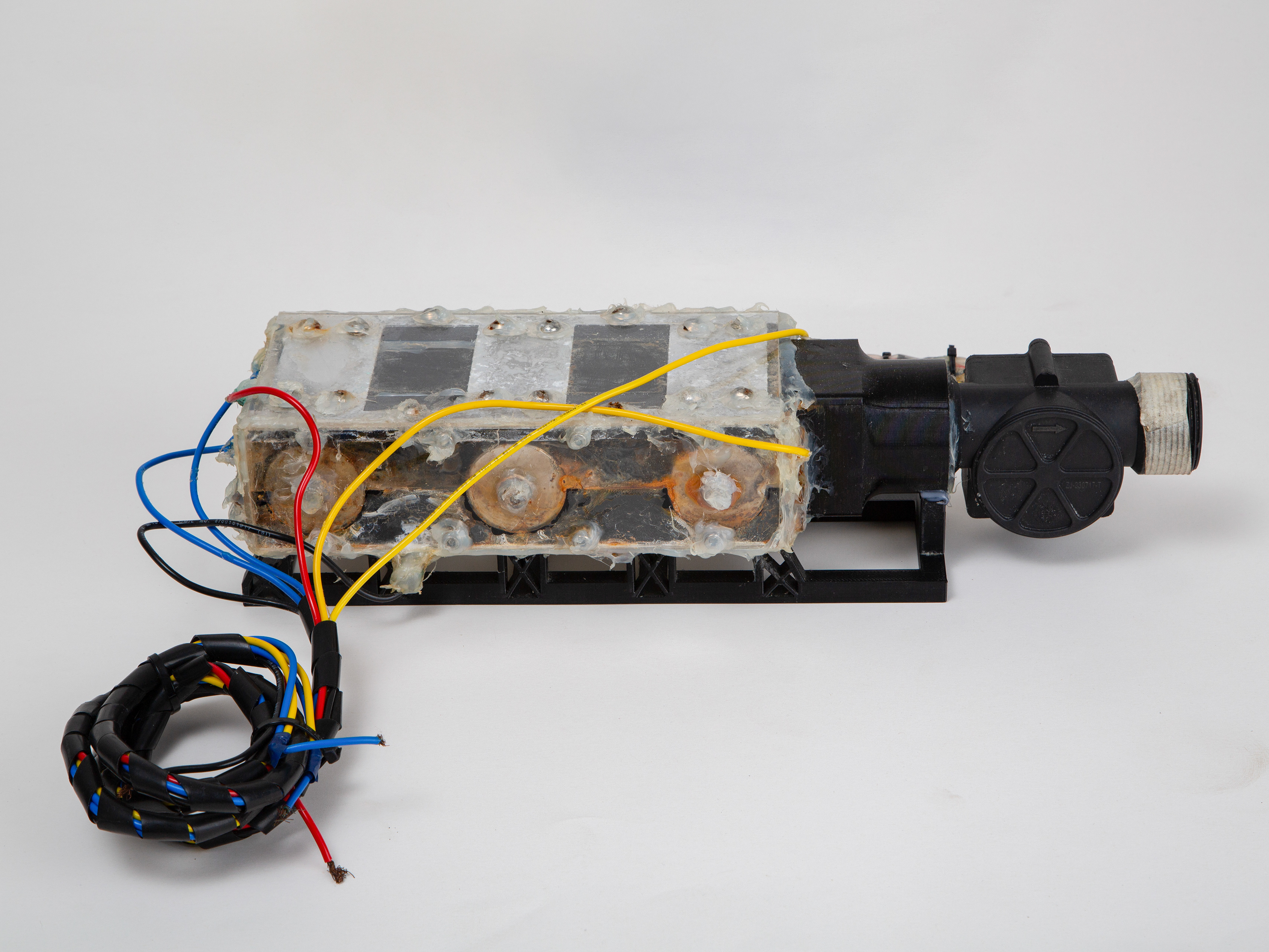
The fusor’s configuration deviated from the traditional spherical design, instead utilizing a lower electrode and a separate upper metal plate. At the center, a stainless steel “egg beater” electrode, connected to a high negative potential, served to accelerate ions toward its inner region. All diodes and capacitors within the voltage multiplier were potted in epoxy to prevent corona or arcing. JB Weld sealed feedthroughs, ensuring vacuum integrity and stable operating conditions, while stainless steel components were selected for their durability and compatibility with low-pressure environments.
Vacuum and Gas Management
Under test conditions, the fusor chamber was evacuated to low pressures using a vacuum pump connected via a dedicated port. A vacuum gauge monitored internal pressure, guiding adjustments to achieve the requisite mean free path for ion motion. Valves and fittings allowed precise introduction of hydrogen or helium, enabling the formation of a sparse plasma. This setup aligned with Farnsworth’s principle: a strongly negative inner electrode and a grounded outer plate creating the field necessary for accelerating ions and potentially inducing fusion reactions in the device’s core.
Testing and Observations
During initial tests at reduced voltages, the fusor did not produce meaningful fusion activity. Issues such as minor air leaks, suboptimal electrode alignments, and limited voltage impeded the formation of the stable plasma conditions needed for significant ion collisions.
Lessons Learned and Future Improvements
Working on the fusor deepened understanding of multi-disciplinary engineering challenges: high-voltage DC generation, vacuum sealing, ionizable gas handling, and electrode design. By confronting practical difficulties, it became evident that incremental improvements—such as incorporating a sight glass for direct plasma observation, employing a neon sign transformer for more consistent voltage supply, and refining electrode geometries—would enhance future performance.
Although the device did not operate as intended, the process of assembling, testing, and analyzing the fusor significantly expanded my skills in high-voltage engineering, vacuum system design, and experimental diagnostics. Armed with these insights, I am better prepared to refine my approach, integrate more robust equipment, and advance the project toward more controlled and insightful experimental outcomes.
